



MOOG POWER & DATA / RUGGED OPTICAL SOLUTIONS
MOOG rugged optical networksTransceivers and integration
TARGET TechNews · Updated
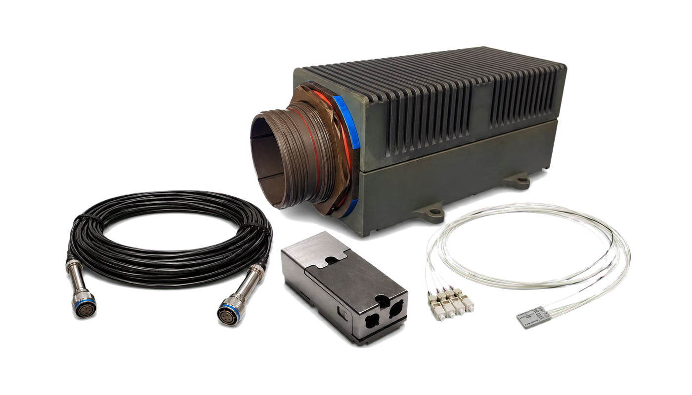
MOOG Rugged Optical Solutions brings together COTSWORKS and Protokraft expertise. Evaluate optical transceivers, fiber interconnect, Ethernet switches, media converters and WDM/MUX against the data-rate, installation and environmental requirements of your network architecture.
SOLUTION PORTFOLIO
A product portfolio shaped around your platform
Every platform brings a different data, environment and integration challenge. The MOOG product portfolio aligns transceiver, interconnect, switching and optical distribution families in one path, helping you build a scalable architecture that supports SWaP and lifecycle priorities.
01
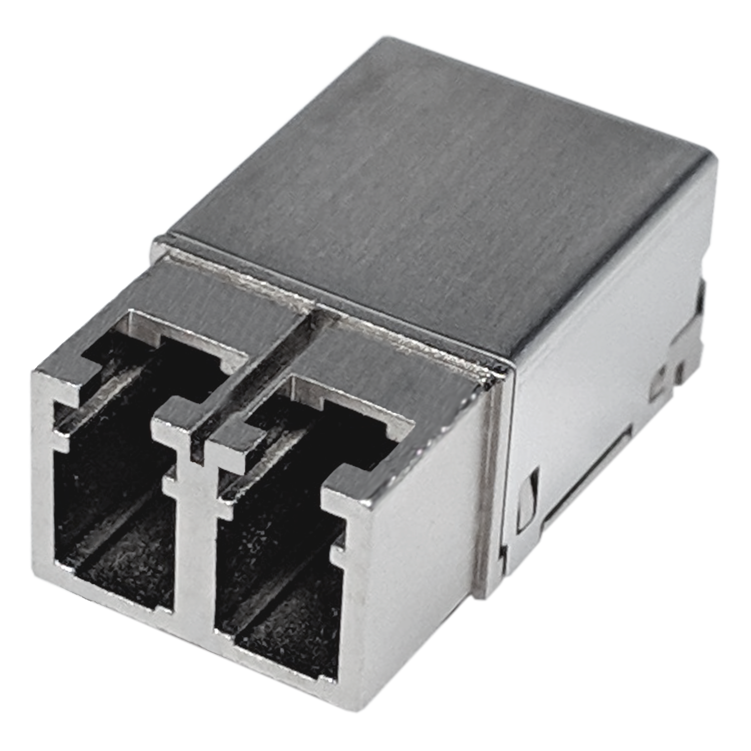
Board-mount optical transceivers
The MOOG board-mount transceiver portfolio offers a choice of form factors and optical interfaces for reliable fiber links on demanding platforms. Match the right family to your data rate, installation and integration priorities.
- Form factor
- Data rate
- Wavelength
02
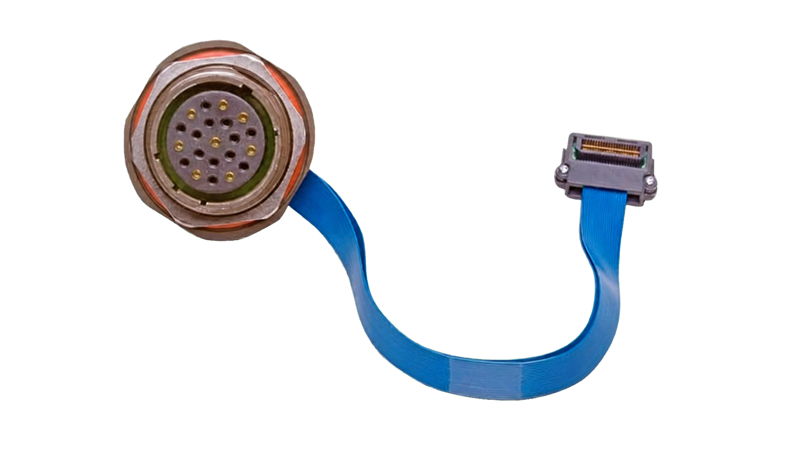
Panel-mount optical transceivers
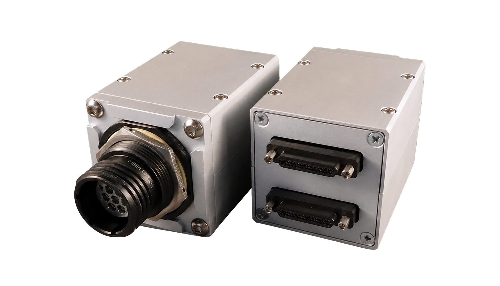
MOOG panel-mount families, including Lightning, bring optical conversion into connector-based packages. Select mounting, channel and interface options that simplify integration around the platform.
- Panel mount
- Multi-channel
- Rugged interface
03
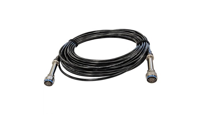
Fiber interconnect and cable assemblies
Termini, connectors and cable assemblies form the physical backbone of an optical network. The right interface supports cleaner integration, easier service and long-term availability across your platform lifecycle.
- ARINC 801
- M29504
- Cable assembly
04
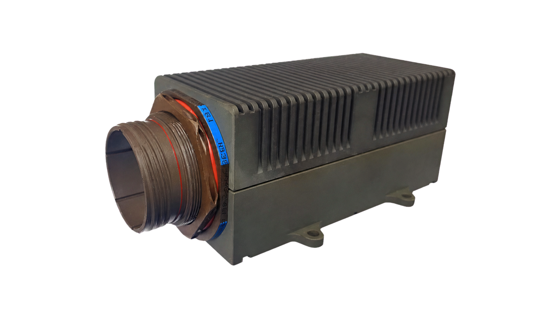
Rugged Ethernet switches
MOOG Ethernet switch families help organize critical data within a scalable rugged network. Align port architecture, speed, power and management options with your platform objectives.
- Fast / Gigabit / 10G
- Managed options
- Rugged enclosure
05
Ethernet media converters
Rugged Ethernet media converters provide a practical bridge between copper and fiber network segments. Fast, Gigabit and 10 Gigabit families help extend fiber reach while preserving the value of existing infrastructure.
- Copper to fiber
- Fast / Gigabit / 10G
- Platform fit
06
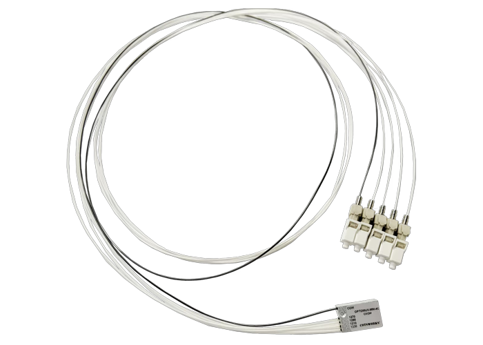
WDM/MUX and passive optical distribution
CWDM and passive components help multiple optical channels share the same fiber infrastructure. Channel planning and packaging options can reduce cabling complexity and make more efficient use of available fiber capacity.
- CWDM
- Optical routing
- Link budget
CONNECTED APPROACH
From the right products to a stronger network architecture
MOOG Rugged Optical Solutions brings transceivers, interconnect, switching, firmware and lifecycle needs into one roadmap, so you can build an optical network that grows with the platform instead of selecting products in isolation.
Understand the need
Align on the platform, protocol, data rate, environment and SWaP priorities.
Select the right family
Evaluate transceiver and optical engine options together with the link budget.
Build the fiber path
Shape termini, connector, fiber and cable assembly choices around installation and service needs.
Scale the architecture
Create room to grow with switching, media conversion, WDM/MUX and FORJ where required.
Verify together
Complete firmware, latency, synchronization and environmental verification against program goals.
APPLICATION AREAS
Where Rugged Optical Solutions makes a difference
Bring the benefits of fiber to mission-critical platforms where high data volume, low weight and dependable performance matter.
SENSOR NETWORKS
Radar, EW and EO/IR
Create an EMI-advantaged, lightweight and scalable fiber network foundation for high data flows from AESA radar, electronic warfare and EO/IR systems.
GROUND SYSTEMS
Tactical vehicles and C4ISR
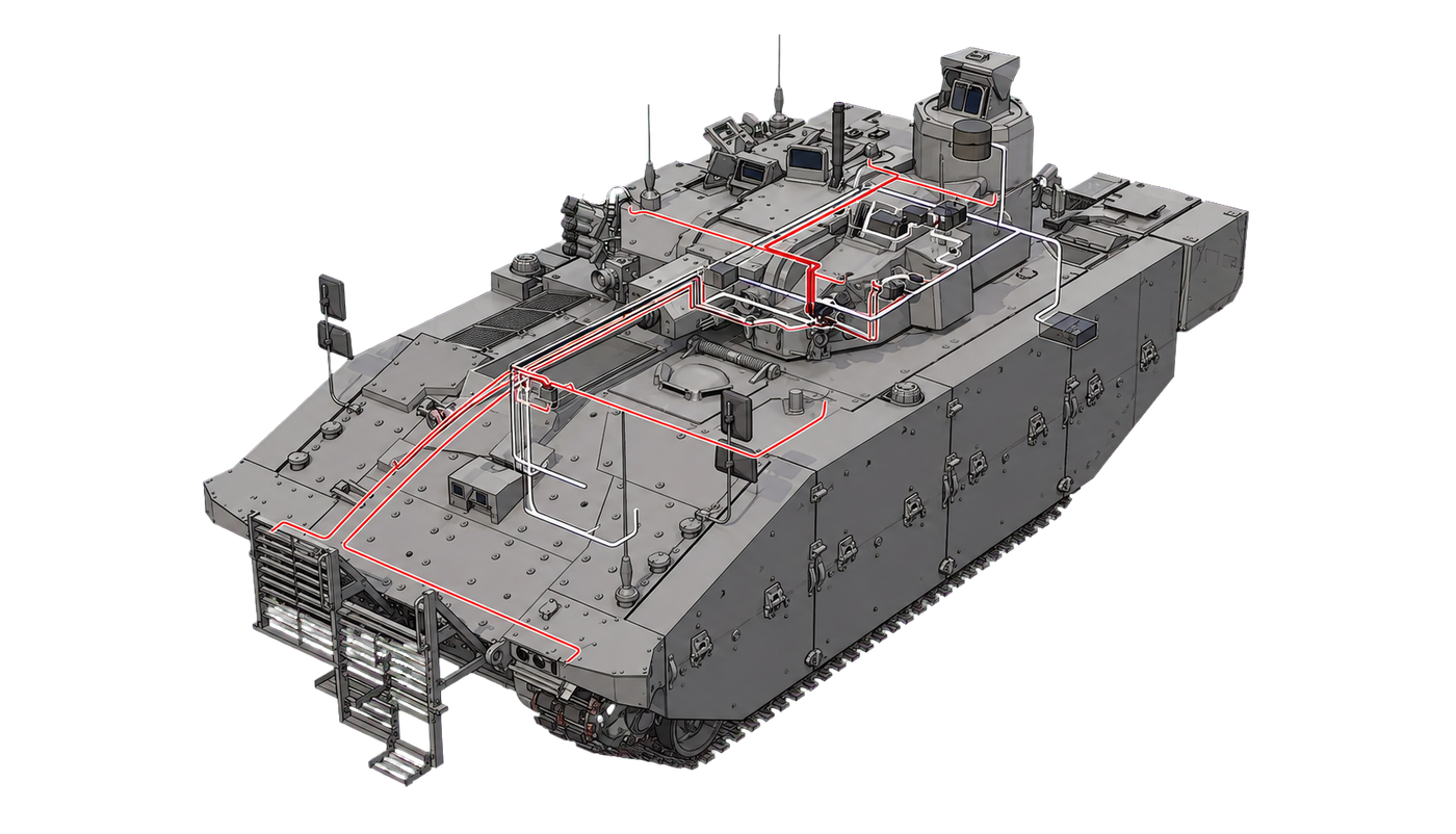
Build a dependable, serviceable and adaptable fiber network across mission computers, cameras, displays and the vehicle backbone.
AIR / SPACE
Avionics and rotating payloads
Create a platform-specific solution for avionics, space and rotating payloads with the right mix of transceivers, interconnect, WDM/MUX and FORJ where required.
Integration decisions
Which component does your rugged optical network need?
Draw where each connection starts and ends: a sensor board, equipment panel, vehicle backbone or rotating interface. Record the protocol, data rate and location of optical conversion for each link. Two products with a similar mechanical connector may have different electrical interfaces or network functions. These boundaries provide a practical starting point for selecting the correct product category.
| Requirement | Category to evaluate | Key selection questions |
|---|---|---|
| Optical conversion on a board | A board-mount transceiver, such as Razor | Are the electrical interface, PCB layout, power and thermal arrangements compatible? |
| Optical conversion at a panel | A panel-mount transceiver, such as Lightning | Does it match the connector, channel count and internal connection layout? |
| Electrical Ethernet to fiber | A compatible Ethernet media converter | Do the electrical and optical interfaces match the required rates and standards? |
| Connecting multiple Ethernet links | An Ethernet switch | Are port count, management functions and backbone capacity sufficient? |
MOOG describes Razor as a surface-mounted PCB assembly with duplex LC, and Lightning as multiple optical transmitter/receiver functions integrated into a MIL-DTL-38999 Series III receptacle. These illustrate mounting approaches; Lightning's connector description does not establish the specification of every MOOG product or qualify a complete platform.
Can a media converter replace an Ethernet switch?
The functions differ. A media converter connects specified electrical and optical Ethernet interfaces, while switch selection addresses how multiple links are switched. If only a change of transmission medium is required, justify any additional switching requirement separately. Verify multiport operation, traffic management and latency requirements against the selected device's documentation.
What belongs in a CWDM link-budget review?
Sharing a fiber between optical channels involves more than adding a multiplexer. MOOG's WDM technical overview describes planning transmitter wavelengths and multiplexing/demultiplexing paths together. Check transceiver compatibility, single-mode or multimode fiber, and connectors for each channel.
The available margin between transmitter output and receiver sensitivity must accommodate fiber, connector, splice and multiplexer losses. Use the selected components' specified operating conditions and the design margin. Sufficient optical power alone does not establish protocol or data-rate compatibility. If the path crosses a rotating interface, include the FORJ as a separate verification item in the complete connection chain.
A short checklist for the design review
- Document each endpoint's protocol, data rate, electrical interface and channel directions.
- Specify fiber type, wavelength, distance, connectors and service access.
- Match power, space, temperature and vibration requirements at part-number level.
- Add cable routing, cleaning/maintenance access and the verification plan to the drawing.
TARGET's MOOG solution page provides related portfolio context. Share your connection diagram and requirements with TARGET to clarify the product categories to evaluate. Final selection remains subject to the current part-number documentation and project conditions.
MOOG SUPPORT IN TURKEY



